LED display remote monitoring should answer three practical questions: Is the display service available, where is an abnormal condition located, and who must act next? A useful system combines supported status data from the LED wall, control chain, power distribution, network, and environment with clear alert rules and an agreed response workflow. It does not replace visual inspection, safe site access, or qualified diagnosis.
Buyers should specify monitoring during system design, not add a generic dashboard after handover. The monitored components, data quality, network security, alert ownership, retention, and acceptance tests all affect whether an alert becomes useful evidence or background noise.
What should LED display remote monitoring cover?
Direct answer: monitor the display’s availability, video and control path, sending and receiving chain, cabinet or module status where supported, power state, relevant environmental conditions, redundancy state, network communication, and event history. For every data point, define its source, normal range or state, alert condition, severity, owner, and verification method.
The exact coverage depends on the installed product and integration. Not every LED system exposes the same telemetry, and a reported “online” state does not prove that correct content is visible. The specification should separate directly measured status, inferred status, and operator confirmation.
What is an LED wall monitoring system?
An LED wall monitoring system is the combination of supported device telemetry, communications, software, alert logic, records, and operating responsibilities used to observe an installed display. It may collect information from video processors, controllers, receiving devices, intelligent distribution equipment, environmental sensors, network infrastructure, and building systems.
Monitoring is only one layer of service management. The customer still needs approved operating procedures, a fault-recovery process, a spare-parts plan, and a support agreement. The LED display maintenance SLA should define what happens after an alert becomes a service incident.
Start with a monitored-system boundary
Draw the complete path from content source to visible image. Include source devices, switching, video processing, control network, sending and receiving chain, display cabinets, distribution, cooling or ventilation, remote access, and any building-management interface. Mark which components are monitored, which provide only a basic heartbeat, and which remain outside the platform.
This boundary prevents misleading conclusions. If the LED controller is online but the upstream source is absent, a display-only platform may report healthy communication while the audience sees no intended content. If a temperature sensor sits in the room rather than inside a cabinet, its reading describes the room—not every internal component. Record those limits in the as-built documentation.
| Monitoring layer | Useful evidence | What it cannot prove alone | Buyer acceptance question |
|---|---|---|---|
| Source and processor | Input presence, selected route, processor communication, preset state where supported | That the full canvas is visually correct | Can the system distinguish no source from a display fault? |
| Control and receiving chain | Device reachability, communication loss, cabinet map, reported errors | That every pixel or module looks normal | Does each reported address match the physical wall position? |
| Power and distribution | Commanded state, branch or cabinet status, alarms where equipment supports them | Electrical safety or power quality beyond the installed instruments | Which states are measured and which are inferred? |
| Environment | Relevant room, enclosure, or cabinet conditions from identified sensors | Conditions in unmeasured locations | Where is each sensor and what action follows an alert? |
| Network and remote access | Connectivity, communication interruptions, session and event records | The health of devices that do not expose telemetry | Who owns the network path and remote-access approval? |
| Visual confirmation | Operator inspection or authorized camera view where permitted | Internal electrical or control health | How is an alert compared with what users actually see? |
Choose signals that support a decision
More data does not automatically produce better monitoring. Every signal should lead to a defined decision: continue observing, ask the operator to verify, switch to an approved redundant path, create a service ticket, schedule maintenance, or follow the site emergency procedure. A metric with no owner or action becomes dashboard clutter.
Useful signals may include communication availability, loss of input, device alarm state, cabinet or receiving-unit status, redundancy change, power state, temperature or humidity where supported and relevant, fan or cooling alarm where available, restart event, configuration change, and remote-login history. Confirm each capability from the selected product and integration instead of assuming that a feature name means the same thing across systems.
How should LED display alert thresholds be set?
LED display alert thresholds should come from manufacturer limits, the approved site design, commissioned baseline data, and the operating consequence. Do not copy a temperature, voltage, packet-loss, or timeout value from another installation without confirming that the sensor location, equipment, sampling method, and environment are comparable.
Define the condition and its duration. A momentary communication interruption may need a different response from a sustained loss. Use delay, persistence, or confirmation logic where appropriate so normal transitions do not generate repeated incidents. State how an alert clears, whether acknowledgement is required, and whether repeated occurrences within a review period become a maintenance action.
Environmental alerts should align with the project’s thermal management and ventilation plan. A room sensor, return-air sensor, cabinet sensor, and processor-room sensor are different evidence sources. Name the location rather than using an ambiguous label such as “screen temperature.”
Design severity and routing before enabling alerts
Group alerts by operational impact, not by the color chosen in the software. Complete loss of a required display, partial loss affecting essential content, loss of redundancy, a single localized defect, environmental drift, and an informational configuration event may require different routes. The business owner should define critical operating periods and acceptable degraded modes.
Each alert needs a named destination and backup path. Define whether it goes to an operator, AV support, facilities, IT, the integrator, or an external service desk. Add escalation rules for an unacknowledged event and define who may change severity. The black-screen recovery plan should use the same terminology so monitoring and operator actions do not conflict.
Add context so an alert is usable evidence
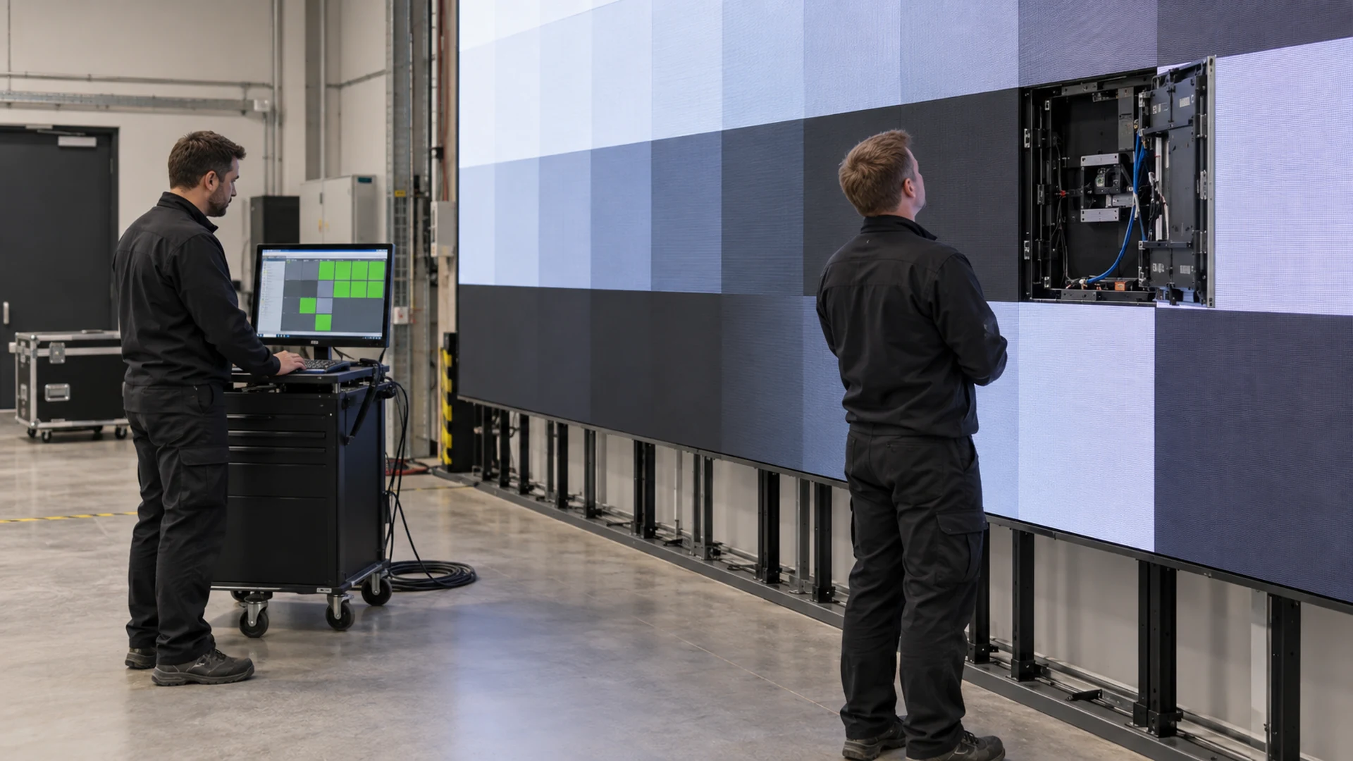
An alert message should identify the site, display, device or physical region, time, observed state, severity, rule that triggered, recent related events, and first verification action. For remote LED screen diagnostics, this context helps the support team distinguish a source issue from a cabinet, control-chain, or site dependency. Where the system supports it, preserve a short event history rather than showing only the current state. A recovered alert can still reveal an intermittent problem that deserves review.
Use consistent asset names across the monitoring platform, field labels, drawings, processor maps, and support tickets. “Cabinet 12” is useful only if the technician can locate the same cabinet without guessing. After authorized module or cabinet work, update the asset and configuration records under the module replacement plan.
Protect the monitoring network and remote access
Monitoring should follow the customer’s cybersecurity and network policies. Define network ownership, segmentation, permitted outbound and inbound connections, user roles, authentication, session approval, log retention, software update responsibility, and removal of access when personnel or suppliers change. Do not use shared credentials inside operating documents or alert messages.
Agree what happens when the monitoring path fails. Loss of the dashboard may be a monitoring incident rather than a display failure, but it removes visibility and may need escalation. If the system relies on cloud access, state who owns internet connectivity, service accounts, subscriptions, and renewal. Remote control permissions should be narrower than read-only monitoring when the platform allows that separation.
Test monitoring during commissioning
An LED display monitoring checklist should be part of commissioning and handover. Do not accept a dashboard solely because devices appear green. Create approved test conditions, observe the physical system, confirm the matching software event, verify routing and timestamps, acknowledge the alert, restore the condition, and confirm that recovery is recorded.
- Verify the asset list, cabinet map, device names, sensor locations, and system boundary.
- Confirm that normal operation produces the expected baseline without unexplained active alarms.
- Trigger only supplier-approved test conditions; never create unsafe electrical, thermal, or structural conditions.
- Match each alert to the physical device or region and record the evidence.
- Test delivery to the primary and backup recipients during the contracted support window.
- Verify acknowledgement, escalation, recovery, event history, time synchronization, and report export.
- Record unavailable telemetry and any condition that still requires manual inspection.
Coordinate these tests with the wider LED display commissioning and handover checklist. The final evidence should identify the tested configuration, date, responsible people, expected result, observed result, open issue, and acceptance decision.
Define retention, reports, and review cadence
Decide how long events, acknowledgements, remote sessions, and configuration changes remain available, subject to the organization’s security and privacy policies. Retention should support warranty discussions, recurring-fault analysis, SLA review, and planned maintenance without collecting unnecessary information.
A useful periodic report shows alert count by type and severity, affected assets, acknowledgement and restoration history, repeat events, monitoring outages, disabled rules, configuration changes, and open corrective actions. Counts need context: a high number may indicate a real fault, a poor threshold, duplicate routing, or unstable communications. Review the cause before treating the total as a performance score.
Questions to include in the RFQ
- Which components and conditions are directly monitored in the proposed configuration?
- Which states are inferred, and which require visual or onsite confirmation?
- How are software addresses mapped to the physical wall and as-built drawings?
- How are thresholds, persistence, severity, routing, acknowledgement, and recovery configured?
- What happens when the monitoring server, network path, or cloud service is unavailable?
- Who owns remote access, licenses, updates, accounts, retention, and periodic review?
- Which acceptance tests and handover records are included in the quotation?
Frequently asked questions
Can remote monitoring confirm that the LED image looks correct?
Not by telemetry alone. Device status can identify communication, power, or reported component conditions, but it may not confirm content accuracy, color uniformity, focus of an external camera, or every visible defect. Combine monitoring with operator inspection or an authorized visual-confirmation method.
Should every monitoring alert create a support ticket?
No. Informational events, brief transitions, and persistent faults may need different treatment. Define which rules create incidents automatically, which require operator verification, and which remain available only for trend review.
Can one platform monitor displays from different manufacturers?
It may be possible, but the depth and meaning of telemetry can differ by product, controller, protocol, and integration. Require a device-by-device capability matrix and test each promised data point in the installed configuration.
Who should own LED display monitoring?
Ownership is usually shared. AV or operations may verify the visible service, IT owns network and access controls, facilities handles environmental or building systems, and the integrator or service provider diagnoses supported equipment. Name one accountable process owner and document every handoff.
Turn monitoring data into an operating decision
Effective LED display remote monitoring is not a wall of green icons. It is a tested evidence path from a measured condition to the correct person and action. Define the system boundary, signal meaning, threshold, severity, route, verification step, record, and escalation before handover.
For a useful supplier discussion, prepare the display configuration, system diagram, site locations, operating hours, critical content periods, network policy, environmental controls, redundancy design, support coverage, and reporting needs. Review KSS Display’s support capabilities and contact the project team to discuss monitoring scope and acceptance evidence for your installation.