A failed LED module can look like a simple swap: remove the dark or damaged section, install a spare, and restore the image. The physical exchange may be quick, but the visible result can still fail. A replacement that fits the opening may differ in LED type, surface finish, brightness response, color behavior, firmware assumptions, or calibration data. On a large uniform image, even a small mismatch can remain obvious.
A useful LED display module replacement plan therefore covers more than spare quantity. It defines compatibility evidence, storage and traceability, safe access, configuration control, visual matching, acceptance, and responsibility. Buyers should agree on these items before handover so an urgent repair does not become an improvised engineering exercise.
Confirm the fault before replacing a module
A visible black area does not always prove that the LED module is defective. A loose connection, receiving-card issue, power interruption, incorrect configuration, or upstream signal problem may create a similar symptom. Replacing a healthy module adds risk without correcting the cause.
Start with the approved operating checks and the site’s LED display black-screen recovery plan. Record the fault position, content state, time, affected area, recent changes, monitoring alerts, and any safe checks already completed. Escalate to a qualified technician before opening cabinets or working near electrical equipment.
The replacement decision should answer three questions: Is the fault localized to the module? Is the proposed spare compatible with this cabinet position? What test will prove the repair is visually and operationally acceptable?
Capture the baseline before anything moves
Before removal, photograph the visible defect and the surrounding image under the normal operating preset. Note the cabinet and module position using the installed asset map. Save relevant monitoring information and confirm the active configuration version. If a technician later needs to compare the repaired area, this baseline is more useful than memory.
The record should connect to the project’s LED display as-built documentation. Cabinet coordinates, signal paths, power groups, module IDs, service direction, and configuration files should describe the same installed system. If field labels and drawings disagree, stop and resolve the conflict before service work proceeds.
A replacement module must match more than size
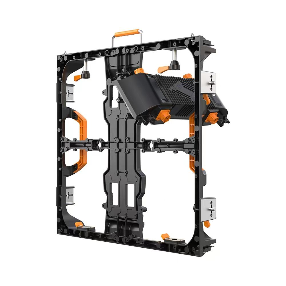
Mechanical fit is only the first compatibility check. A spare must suit the installed cabinet, mounting method, connector arrangement, electrical design, control architecture, and intended visual performance. Buyers should request a documented compatibility statement rather than rely on a familiar-looking face or matching outer dimensions.
On smaller screens, swipe horizontally to view all columns.
| Check | Evidence to compare | Risk if ignored |
|---|---|---|
| Mechanical interface | Module dimensions, mounting points, orientation, depth, service tool, and cabinet opening | Poor seating, damaged connectors, uneven face, or unsafe retention |
| Electrical interface | Power requirements, connector position, pin arrangement, and cabinet design | Failure to operate or damage to components |
| Control compatibility | Receiving-card relationship, scan behavior, driver assumptions, firmware, and parameter file | Wrong mapping, unstable output, or unusable grayscale |
| Optical construction | LED package, pixel arrangement, mask design, surface color, and viewing behavior | A patch that looks different even when nominal color values match |
| Production traceability | Supplier part code, production or matching group, inspection record, and storage history | Unknown variation and difficult root-cause analysis |
| Calibration status | Module-level correction data, wall calibration workflow, and approved baseline | Visible brightness or color discontinuity |
This is why a planned stock of spares is usually more reliable than sourcing an apparently similar module years later. The LED display spare-parts planning guide explains how quantity, storage, ownership, and replenishment should be defined during procurement.
Account for production and operating differences
Two compatible modules can still look different. LED components and masks may vary between production groups, while installed modules change through operating hours, brightness settings, temperature, cleaning, dust, and environmental exposure. A protected spare stored in a case has not experienced the same history as the wall.
Do not reduce spare LED module matching to one label. Ask how the supplier groups modules for visual compatibility, what traceability is retained, how calibration data is managed, and what adjustment process is expected after installation. For critical uniform backgrounds or camera use, define a stricter visual review than for content where small local differences are less noticeable.
Use a controlled LED wall module replacement sequence
- Confirm authorization, maintenance window, safety procedure, access method, and responsible technician.
- Record the fault, position, configuration state, and visible baseline.
- Verify the spare part identity, compatibility evidence, calibration record, and condition.
- Protect the work area, display face, nearby modules, and removed part.
- Isolate or place the system in the approved service state before opening or disconnecting equipment.
- Use the correct service tool and support the module so connectors and cables do not carry its weight.
- Inspect the opening, mating connectors, alignment surfaces, and retention points before installing the spare.
- Seat and connect the module according to the approved procedure, then restore the system in a controlled order.
- Load or confirm the correct parameters and correction data before judging the image.
- Run the agreed operational and visual checks, update records, and quarantine the removed part for assessment.
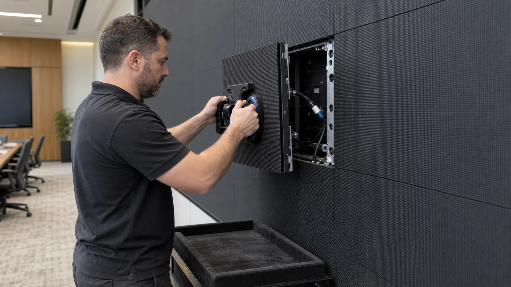
The sequence must be adapted to the actual product and site. A manufacturer may define product-specific service steps, while the integrator, electrician, facilities team, or local safety authority may control isolation, access, lifting, or work-area requirements. A generic article cannot replace those instructions.
Check LED color calibration after replacement
Begin with simple test content that makes discontinuities easy to see: dark fields, mid-level neutral tones, bright fields, primary colors, smooth gradients, and relevant real content. Review the repaired area from normal audience positions, not only from the service distance. If the display is used on camera, include the approved camera setup and operating preset.
Look for more than a direct color difference. Check seams, module height, surface reflection, mask texture, dark-state appearance, low-level uniformity, brightness transition, and behavior as content changes. A module that looks acceptable on a bright image may remain visible on gray or near-black content.
Any adjustment should follow the approved calibration workflow. Do not compensate for a hardware or seating problem by forcing extreme local correction. The LED color uniformity and calibration acceptance guide provides a broader framework for defining test content, viewing conditions, evidence, and approval responsibility.
Maintain LED module inventory traceability
A module inventory should identify the supplier part code, matching group, serial or internal asset ID, calibration status, received condition, storage location, issue date, installed position, removal reason, and repair outcome. The physical label, inventory record, service ticket, and cabinet map should use consistent identifiers.
After replacement, do not return the removed module to good stock without a clear disposition. Mark it as awaiting diagnosis, repairable, repaired and tested, or rejected. Record which spare position is now empty and whether replenishment is required. This prevents a failed or unmatched part from quietly re-entering service during the next incident.
Storage conditions matter too. Keep modules in suitable protective packaging, with electrostatic and environmental controls appropriate to the product. Avoid pressure on the LED face, unsupported stacking, contamination, mixed identities, and unrecorded borrowing between projects.
Define warranty and responsibility before the first failure
The contract should state who confirms a module fault, who may remove it, who supplies the spare, who transfers calibration data, who performs visual matching, who pays for access, and what evidence is required for a warranty claim. These responsibilities may sit with different parties.
Buyers should also clarify whether unauthorized repair, mixed components, field soldering, altered parameters, or poor storage can affect coverage. Compare the practical service path using the LED display warranty and support guide, not the headline warranty period alone.
Put the replacement plan into the RFQ and acceptance scope
- Define the spare module quantity, compatibility grouping, packaging, ownership, and replenishment method.
- Request part codes, traceability fields, configuration requirements, and calibration-data handling.
- State front- or rear-service access, tools, work-area protection, and locally assigned safety duties.
- Agree on the replacement procedure, training evidence, response path, and warranty documentation.
- Define visual test content, viewing positions, operating presets, camera checks when relevant, and approval authority.
- Require the cabinet map, inventory, configuration archive, and service history to be updated after each change.
These deliverables should be inspected when the system arrives and during handover. The LED display receiving inspection checklist can help the buyer verify quantities, packaging, visible condition, identity, and evidence before parts disappear into site storage.
Prepare a useful supplier discussion
For a useful replacement plan, provide the display application, screen dimensions, pixel pitch, cabinet and module identification, service direction, operating environment, expected content, camera use, critical uptime periods, installed configuration, spare inventory, storage conditions, destination, and required support response.
KSSdisplay can review the display-side information needed for the project discussion and help identify the questions that should be resolved before handover. Use the support resources for service context, or contact KSSdisplay with the installed-system details, fault evidence, module identity, project location, and schedule.
Conclusion
An LED display module replacement plan turns a rushed swap into a controlled maintenance process. Confirm the real fault, preserve the baseline, verify compatibility, use safe product-specific service steps, apply the correct configuration and calibration data, test the visible result, and update the inventory. The best replacement is not merely the part that powers on. It is the part that fits the system, performs acceptably in real content, and remains traceable for the next service decision.
Frequently asked questions
Can any module with the same dimensions replace the original?
No. Dimensions do not confirm mounting, connector, electrical, control, optical, or calibration compatibility. Use the supplier’s documented compatibility evidence for the installed cabinet and configuration.
Why can a new spare module look brighter than the wall?
The spare and installed modules may have different production characteristics, storage histories, operating hours, surface conditions, or correction data. The cause should be identified before visual adjustment is approved.
Should calibration be performed after every replacement?
The required process depends on the product, existing correction data, visual result, application, and acceptance criteria. At minimum, verify that the approved data is applied and review the repaired area with suitable test content.
What should happen to the removed module?
Give it a recorded status and protected location. Diagnose it under the approved service process, then mark it as repaired and tested, awaiting work, or rejected before it can return to stock.
How should buyers accept a module replacement?
Confirm secure installation, normal operation, correct parameters, visual performance on agreed test content, acceptable appearance from normal positions, and complete updates to the service, inventory, and configuration records.