LED display light sensors should be approved as part of a complete brightness-control system, not as standalone accessories. Confirm the sensor and controller combination, choose a representative mounting position, define the relationship between ambient light and screen output, and test normal changes plus sensor failure. A sensor that reports a changing value has not, by itself, proved that the display will dim appropriately at dusk.
For an outdoor wall or a retail facade, the useful acceptance question is: does the installed screen remain readable while respecting the project’s agreed brightness and operating-hour limits? This requires evidence from the sensor, control rules and physical display together. The guide below is a commissioning framework for buyers and integrators, not a universal brightness curve, compliance specification or report of a completed KSS installation.
Separate three values before discussing automatic brightness
Ambient illuminance, screen luminance and a software brightness percentage are different values. The sensor observes light in its surroundings. The control system uses that observation to select a setting. The physical screen then produces the output that matters to the viewer. Record these stages separately in the project brief.
Konica Minolta’s explanation of illuminance and luminance identifies lux as the unit of illuminance and candela per square meter, also called a nit, as the unit of luminance. An ambient reading in lux is therefore not a measurement of the screen’s luminance. Do not use the two units interchangeably in a quotation or acceptance report.
Treat the controller percentage as a command rather than a certified output measurement. Record it alongside the screen measurement where quantitative acceptance is required. A photograph or the position of a software slider cannot establish an agreed luminance value without the appropriate measurement method.
Set the display’s operating requirements first. The LED display brightness specification guide addresses the site and viewing conditions that should inform supplier discussions. Automatic control implements those requirements; it does not decide them independently or make the maximum advertised brightness the correct setting for every hour.
Confirm the complete sensor-to-screen control path
Ask the integrator to name the exact sensor, compatible interface, controller, relevant software version and controlled display. Include the cable type, permitted run, mounting hardware and any required accessory in the quotation. “Auto brightness included” is too vague if the proposal leaves out the sensor or relies on an unconfirmed interface.
As one model-specific example, NovaStar’s NS060 specification, version 1.1.4, describes connection to compatible sending, asynchronous or multifunction cards for ambient monitoring and automatic brightness adjustment. It states that the sensor must be in the same environment as the LED display. Check the document and interface for the equipment actually supplied; this example does not establish compatibility with every LED controller.
Identify where the automatic decision is made. Is the curve stored locally in the controller, applied by a management platform, or dependent on another service? Ask what remains operational when remote access is unavailable. Do not assume that a cloud publishing system either controls brightness or is necessary for every local adjustment.
Also identify the scope of one control command. One sensor may be assigned to one display, a group of cabinets or a wider device group, depending on the system. Separate facades with different sunlight exposure should not inherit one site’s policy without evaluation. For an outdoor LED display project, include this control-system boundary when comparing equipment and commissioning scope.
Choose a position that represents the display environment
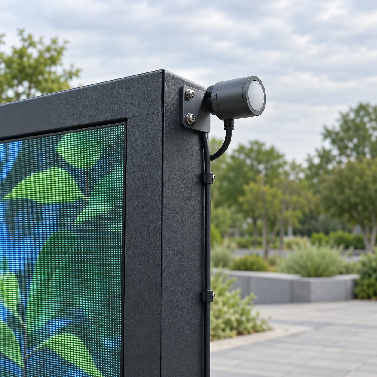
Select the mounting location with the integrator using the sensor manufacturer’s instructions. Record its orientation, height, distance from the active screen and nearby obstructions. A convenient place inside a service cabinet is not automatically representative of the light around the display face.
Inspect the location during the conditions the installation must handle. A canopy, tree or neighboring structure can put the sensor in shade while the screen faces stronger daylight. Reflected sunlight, nearby lighting or light from the display itself may influence the reading. Treat these as placement risks to investigate, not as proof that a particular sensor is faulty.
Before permanent approval, compare readings and screen behavior at the proposed location with the relevant viewing environment. If the values appear inconsistent, ask the integrator to review placement and orientation before adjusting the entire curve to compensate. Document why the chosen point represents the operating case.
Keep service access and outdoor installation details in scope. Confirm the applicable enclosure and connector requirements, cable support, manufacturer-approved routing and inspection access. A component specification does not certify the completed mounting arrangement. The commissioning photograph should show enough context to locate the sensor later, not only a close-up of an unidentified housing.
Define the curve, limits and control priorities
Agree what the screen should do in bright daylight, changing daylight, dusk and darkness. Use these conditions to develop a site-specific mapping with the integrator. Do not copy another screen’s lux thresholds or output percentages solely because its sensor has the same model number.
NovaStar’s MBOX600 Pro user manual provides a concrete example of fixed and ambient-light brightness rules, a brightness mapping table, reporting settings and a specified output when the light sensor fails. These are documented features of that configuration, not a promise that another controller offers the same controls. Require the supplier to demonstrate the equivalent functions in the proposed system.
Set any agreed minimum and maximum operating output, and identify how they are enforced. Ask whether time-based rules, manual overrides, sensor mappings and equipment-protection policies can interact. The same manual describes temperature-controlled brightness taking priority under its specified conditions. For your selected system, request the actual priority order rather than assuming the last setting entered always wins.
Record how quickly readings are updated and how the display responds. Where filtering, transition delays or hysteresis are available, agree and test them. Hysteresis uses different switching thresholds for rising and falling input, helping avoid repeated switching around one boundary. If that function is unavailable, ask which supported behavior will prevent distracting fluctuations; do not invent a feature in the purchase specification.
Keep clock-based dimming aligned with local operating hours. A sensor’s reading does not establish which time zone a schedule uses. The time-zone scheduling checklist helps separate clock configuration from daylight response. Confirm the intended interaction between scheduled limits and the ambient-light policy.
Test transitions instead of one daylight demonstration
Use a known display configuration and a repeatable content pack. Include representative campaign material as well as agreed measurement content when needed. Record the sensor reading, active control mode, commanded setting and visible or measured screen response at each stage.
Start with normal ambient conditions, then use a manufacturer-approved test method to exercise the relevant input ranges. A temporary shaded condition can help demonstrate that a reading changes, but it is not a substitute for observing the installation through the real day-to-night transition. Keep the test scope explicit.
The following matrix lists acceptance cases, not prescribed thresholds or claimed test results. The buyer and integrator should fill in the required output, transition behavior and observation period before the witnessed test.
On smaller screens, swipe horizontally to view all columns.
| Test case | What to observe | Evidence to retain |
|---|---|---|
| Representative daylight | Sensor value and appropriate screen output | Conditions, active rule and output record |
| Daylight entering shade | Response without an unintended mode change | Input change and transition observation |
| Dusk to darkness | Agreed lower-output policy takes effect | Time, ambient reading and screen result |
| Input near a curve boundary | Stability under small variations | Repeated readings and setting changes |
| Scheduled limit or override | The agreed control priority is followed | Active modes, operator action and result |
| Sensor failure test | The approved fallback behavior occurs | Fault indication, output and recovery |
| Approved restart | Intended rules and configuration return | Before/after configuration and result |
Observe the output from the relevant viewing positions, not only from the controller workstation. Check whether normal content remains understandable at the approved lower settings. The content readability guide covers message and template approval; a dimming test should not turn unreadable artwork into an accepted campaign.
When a test fails, preserve the input and configuration evidence. Separate an unexpected sensor value from a wrong rule, a conflicting override or an output problem. Changing the curve, mounting point and manual setting simultaneously makes it harder to establish what corrected the behavior.
Agree sensor failure and recovery before handover
Ask what the selected system considers a sensor fault and which conditions it can actually detect. A disconnected sensor, an old reading or an implausible value may be handled differently. Do not assume that a frozen value will always generate an alarm or that the controller automatically selects the most suitable nighttime setting.
Define the fallback output or operating state with the site owner and integrator. It should respect the approved project limits while supporting the application’s requirements. “Keep the last setting” and “use a fixed fallback” have different consequences if the problem starts in daylight and continues after dark. Neither is a universal answer.
Test failure using the supplier’s safe procedure on a test setup or during an approved maintenance window. Do not disconnect powered wiring or alter protective functions as an improvised demonstration. Confirm how a fault is reported, who receives it, and what can be done remotely versus on site.
Recovery deserves its own check. Does automatic control resume immediately when a valid sensor reading returns, after a delay, or only after operator action? Record the actual behavior and verify that a temporary manual setting does not remain unintentionally active. Connect these actions to the remote monitoring response plan where the project uses one.
Make the handover record useful for the next technician
Save the sensor and controller identifiers, software versions, mounting-location photographs, cable details, approved mapping, operating limits, update behavior and priority rules. Include any differences between sites. A screenshot showing only “automatic enabled” leaves too much unresolved for future troubleshooting.
The test report should name the configuration, content, conditions and results. Mark unobserved conditions as pending rather than implying that a short commissioning visit covered every season. If a real dusk observation is needed after initial setup, assign an owner and completion date in the acceptance record.
Agree who may change brightness settings and how changes are documented. A temporary event override should have a responsible operator and an agreed route back to normal control. Repeat the relevant checks after a sensor relocation, controller replacement, major software change or materially changed surrounding lighting.
Include periodic inspection in the service scope. Ask the manufacturer how the sensor surface and housing should be maintained, and assign inspection of obstructions, mounting and cable condition. Do not prescribe solvents or cleaning methods that the exact device documentation does not support. A saved curve cannot correct a sensor that is later covered or moved.
Questions to resolve before ordering
Can an ambient light sensor measure the display’s brightness?
Not merely by reporting ambient illuminance. Lux describes light arriving at a surface, while screen luminance is expressed in cd/m² or nits. Confirm the sensor’s actual measurement function and use a suitable screen-output measurement method where the project requires quantitative acceptance.
Can several LED displays share one sensor?
Only if the control system supports the intended assignment and the location represents the affected displays sufficiently for the project. Different orientations, shading and operating limits can require separate policies or sensors. Ask for the topology and site-specific acceptance evidence instead of assuming one reading fits the entire fleet.
Does automatic dimming guarantee a particular energy saving?
No project-specific saving can be established from the presence of a sensor alone. Actual results depend on operating hours, content, approved output levels and system behavior. If energy savings are part of the business case, agree the measurement period, baseline and metering method rather than accepting an unsupported percentage.
Put automatic dimming in the project brief
LED display light sensors are useful when their readings lead to an agreed, verified screen response. Specify compatibility, placement, mapping, priorities and failure behavior together. Preserve the commissioned configuration and the evidence that supports it, then make later changes traceable.
For a KSS Display discussion, provide the application, screen dimensions and orientation, daylight and surrounding-light conditions, operating hours, agreed brightness limits, proposed controller, sensor locations and maintenance-access constraints. Send your LED display project requirements so the display, control equipment and commissioning responsibilities can be reviewed in the same scope. Confirm final thresholds and supported functions with the selected equipment’s documentation and the responsible integrator.