LED display latency should be specified for the signal path the audience will actually use, not accepted from a processor’s headline figure alone. Define the starting event and the visible endpoint, identify the operating mode and frame rate, then measure the completed route. Check audio-video synchronization separately at agreed audience positions. A low processor delay does not, by itself, establish low camera-to-screen delay or correct lip sync.
This guide is for buyers, AV integrators and venue teams planning live camera feeds, presentations and synchronized playback. It explains what to request before ordering and what to retain at handover. The examples are planning tools, not reported KSS test results, a universal acceptable-delay limit or a substitute for equipment-specific commissioning instructions.
Start with the experience that needs to stay responsive
A loop of silent promotional content and a live image of a speaker do not have the same timing priorities. Begin by listing the actual uses: local playback, camera magnification, interactive demonstrations, remote participants, recording and streaming. Identify which uses are required together rather than approving each on an isolated bench setup.
For a live camera feed, the relevant question may be how far the screen image trails the event in the room. For a prerecorded interview, the priority may be the relationship between the on-screen mouth movement and the accompanying sound. A system can meet one requirement without meeting the other. Write both outcomes into the acceptance scope when both matter.
For permanent indoor LED display projects, record the normal audience area, presenter position and audio arrangement before selecting the processing route. If visitors can connect their own sources, agree on supported connection methods and test examples. Do not extend an approval for the venue’s dedicated player to every guest laptop or wireless presentation system.
Define the boundary behind every latency claim
Ask the supplier where its quoted timing starts and stops. Possible boundaries include a controller input to visible LED output, a camera event to the displayed camera image, or a user action to the visible application response. These are different measurements. Keep the boundary, unit and configuration next to the number whenever it appears in a proposal.
Brompton Technology’s Ultra Low Latency data sheet defines its video-delay boundary from the final cycle of a source frame at the processor input to the first cycle lighting an LED with that frame. That does not include the entire upstream camera or application workflow. Its stated one-frame mode for Tessera SX40 and S8 also has source and pixel-capacity conditions; it is not a one-frame guarantee for every completed installation.
Translate frame-based figures into time at the stated frame rate. One frame at 50 frames per second spans 20 milliseconds; at 60 frames per second, it spans about 16.7 milliseconds. These follow from 1,000 divided by frames per second. They describe a frame interval, not a measured result for a particular wall, and they should not be confused with the display’s LED refresh specification.
Keep timing acceptance distinct from the camera flicker and refresh-rate checks. A camera-friendly image and a responsive signal path are separate requirements. Passing a flicker inspection does not provide the missing latency measurement.
Map the video and audio routes before choosing a shortcut
Document the actual video path from the source through any camera processing, converter, switcher, scaler, transport device and LED processor to the wall. Draw the accompanying audio path separately, including where sound is extracted, processed and reproduced. Identify any recording, streaming or remote-meeting branch rather than treating it as the same destination.
Ask the integrator to mark which stages are included in a component specification and which require system-level testing. Where a delay budget is used, distinguish estimates from measurements. Adding several nominal figures can support planning, but it should not be presented as a measured guarantee for the installed configuration.
Review the complete operating mode, not just the equipment model. A proposal should state whether scaling, frame-rate conversion, synchronization, image rotation or other required processing is active. Have the supplier explain any dependency between a latency option and those functions. Removing a needed function to obtain a better number may change the agreed picture or source compatibility.
The LED video processor selection checklist helps compare the wider scope. For timing-sensitive use, add the required processing mode and measurement boundary to that comparison so offers are evaluated on equivalent conditions.
Check what a low-latency mode gives up
Do not assume that every mode with a similar name preserves the same features. The Low Latency Mode section in Brompton’s Tessera user manual, version 2.2 describes model-specific behavior: for the T1 and M2, low-latency operation disables scaling, deinterlacing and frame-rate conversion. Other processor families have different arrangements. Confirm the applicable current manual and firmware for the proposed equipment.
The procurement decision is whether the low-delay configuration still delivers the intended content layout and source workflow. Request a demonstration using the planned canvas, actual source mode and required processing. Keep supported limitations visible in the quotation rather than discovering them after the content team has built its files.
If the design requires a different source output, verify that output across the real connection route. The EDID and HDMI commissioning guide addresses capability exchange, detected input and image mapping. A low-latency preset is not evidence that an unsupported source format has become usable.
Measure the installed camera-to-screen path
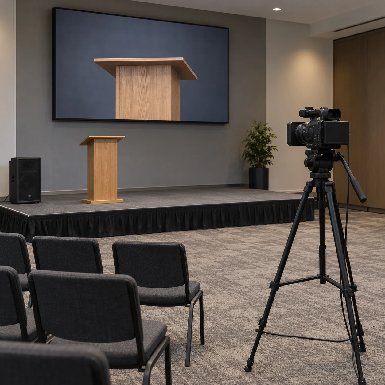
Agree on the measurement method and acceptance criteria before the demonstration. Ask the integrator to specify the starting event, observation point, test equipment, timing resolution and repeat procedure. Use a method suitable for the promised accuracy. A visual impression that the image feels fast is useful feedback, but it is not a numerical measurement record.
For a camera workflow, test the actual camera mode and full intended route. A test that substitutes a direct generator at the LED processor input cannot establish the camera-to-screen result. Likewise, a capture taken before the physical LED output does not automatically demonstrate the complete visible path. State these boundaries explicitly in the report.
Retain the test arrangement and enough evidence to reproduce it. Record source and processor settings, active frame rate, equipment identifiers, software or firmware versions, relevant processing options, observations and any excluded branches. Repeat the agreed test rather than selecting only the most favorable observation. Have the specialist explain the measurement uncertainty and any material variation.
If recorded footage is used as evidence, document its acquisition and analysis method. Do not claim finer accuracy than the method supports or present an edited comparison clip as a complete timing report. A photograph can show the setup; a still image alone cannot verify a latency value.
Assess lip sync where people watch and listen
Biamp’s explanation of lip sync and delay equalization distinguishes the timing offset between audio and video from overall system latency. Its TesiraLUX guidance also states that external elements, such as camera latency, are outside the system’s own latency calculation and need separate accounting. An automatic synchronization feature should therefore be evaluated within its documented boundary, not assumed to cover every connected device.
Ask the AV specialist to test a suitable synchronized picture-and-sound reference through the actual playback route, then representative speech content. Record whether audio leads or follows the displayed event and which audience position the observation represents. Keep the sign convention explicit; a setting described only as “minus delay” is easy to misinterpret during support.
Agree the criteria for the intended room and use. Do not copy a product’s internal alignment specification into a venue-wide acceptance promise. Where the audience can see the live speaker as well as the camera image, the review should consider that experience alongside the reproduced sound. Keep speaker placement and audio-system adjustments under the responsible AV specialist’s control.
Audio alignment and responsiveness are not interchangeable solutions. Adding delay to one path may improve their relative alignment without reducing the time taken by the other path. If the picture itself is too late for the agreed use, ask the integrator to review the video route rather than reporting a lip-sync adjustment as proof that camera-to-screen latency improved.
Approve normal operation, not only one demonstration
Define which sources, routes and modes must pass. Include the primary camera, the dedicated media player and any supported guest connection that matters to the project. Test relevant input changes and the documented restart procedure, then verify that the accepted timing-related configuration is restored. Keep temporary diagnostic settings separate from the production baseline.
For media playback, use files that have already passed the video format approval process. This keeps a decoding problem from being confused with a timing issue. Still check the sound-and-picture relationship at the final destination; successful playback is not the whole acceptance decision.
Use this matrix to agree on evidence and responsibility. It is a blank project framework, not a set of measured results or universal performance thresholds.
On smaller screens, swipe horizontally to view all columns.
| Approval item | Evidence to retain | Boundary to state |
|---|---|---|
| Processor delay claim | Manufacturer document and applicable operating mode | Controller input to the specified LED output event |
| Live camera performance | Reproducible measurement record and uncertainty | Physical reference event to visible camera image |
| Playback lip sync | Test reference, lead/lag result and audience location | Reproduced picture relative to reproduced sound |
| Mode and source changes | Tested route list and restoration observations | Only the sources and transitions actually assessed |
| Handover baseline | Saved configuration, versions and named owner | Changes that require review or retesting |
Assign one person to coordinate the overall timing result, even when the camera, display and audio packages come from separate suppliers. Each supplier should identify its own scope, but the buyer also needs an owner for the completed experience. Unresolved exceptions should remain visible rather than being absorbed into a general “system passed” statement.
Preserve the baseline when the system changes
At handover, retain the approved signal routes, configuration files, test evidence and operator instructions together. Note which settings users may change and which require integrator review. Give support the original acceptance conditions so a later complaint can be compared with a known configuration instead of a remembered demonstration.
Request a review after changes to a camera mode, source application, transport route, processor firmware, scaling arrangement or audio routing that may affect timing. The integrator should define the necessary retest scope. A newly installed replacement device is not automatically covered merely because its connectors match the previous unit.
Keep local display acceptance separate from a remote stream or meeting feed. If that branch is in scope, assess its own endpoints and conditions. Do not extend an approved local result to an untested remote audience, recording or network path.
Questions buyers ask about LED display latency
Is a one-frame processor specification enough for live camera use?
No. Establish the manufacturer’s measurement boundary and mode conditions, then assess the complete camera-to-visible-screen path. Include the actual source, transport and required processing. The processor figure is one piece of evidence, not a substitute for the installed-system test.
Does increasing LED refresh rate guarantee less input lag?
Do not use the refresh figure as that guarantee. Ask for the delay measurement, operating mode and source frame rate that apply to the complete route. Evaluate flicker behavior and latency with their respective checks rather than assuming one headline specification establishes both.
Can one audio-delay setting cover every source?
Only claim coverage for the routes and operating conditions that have been assessed. Include the source list and any automatic alignment behavior in the test scope, and verify the outcome at the agreed audience locations. A successful player test should not silently approve a different live camera or remote-meeting route.
Put a measurable timing scope in the RFQ
LED display latency is most useful as a defined acceptance requirement: a specific experience, stated endpoints, an approved mode and reproducible evidence. Keep relative audio-video alignment distinct from total delay, and retain the conditions behind every accepted result.
For a KSS Display project discussion, provide the application, wall dimensions and pixel canvas, audience positions, camera and player models, signal-route diagram, required processing functions, audio arrangement, supported guest inputs and intended timing criteria. Send your LED display project requirements so the display scope and integration responsibilities can be reviewed together. Confirm final measurement methods and acceptance limits with the selected equipment suppliers and responsible AV integrator.